
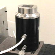
Rapid Compression Facility
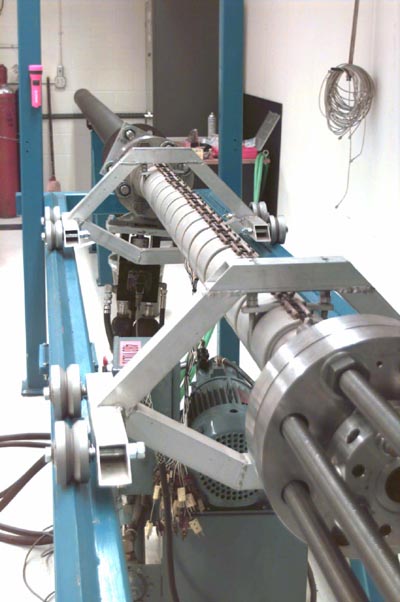
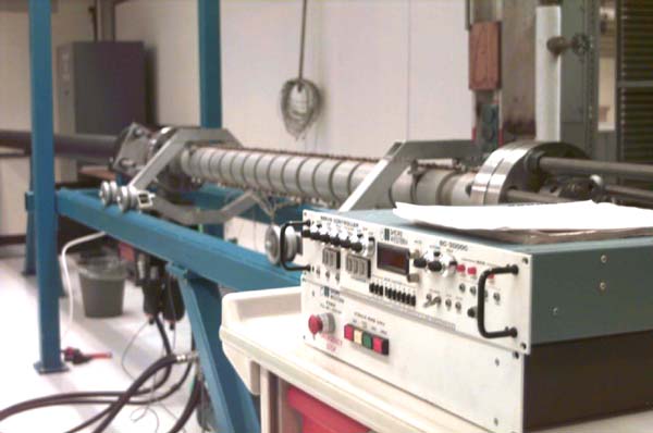
Our rapid compression facility is an excellent tool for isolating and studying chemical kinetics over a broad range of thermodynamic conditions relevant to a variety of combustor systems. Global kinetic metrics such as ignition delay times and activation energies are determined via pressure measurements taken at 100 kHz. High speed imaging, fast gas sampling of intermediate species, and laser spectroscopy techniques can be applied to further probe the combustion chemistry as it occurs.
Recent publication:
D. M. A. Karwat, S. W. Wagnon, M. S. Wooldridge, C. K. Westbrook. “Low-Temperature Speciation and Chemical Kinetic Studies of n-Heptane,” Combustion and Flame 116 (2012) 12406-12421.
Optical Engine Facilities
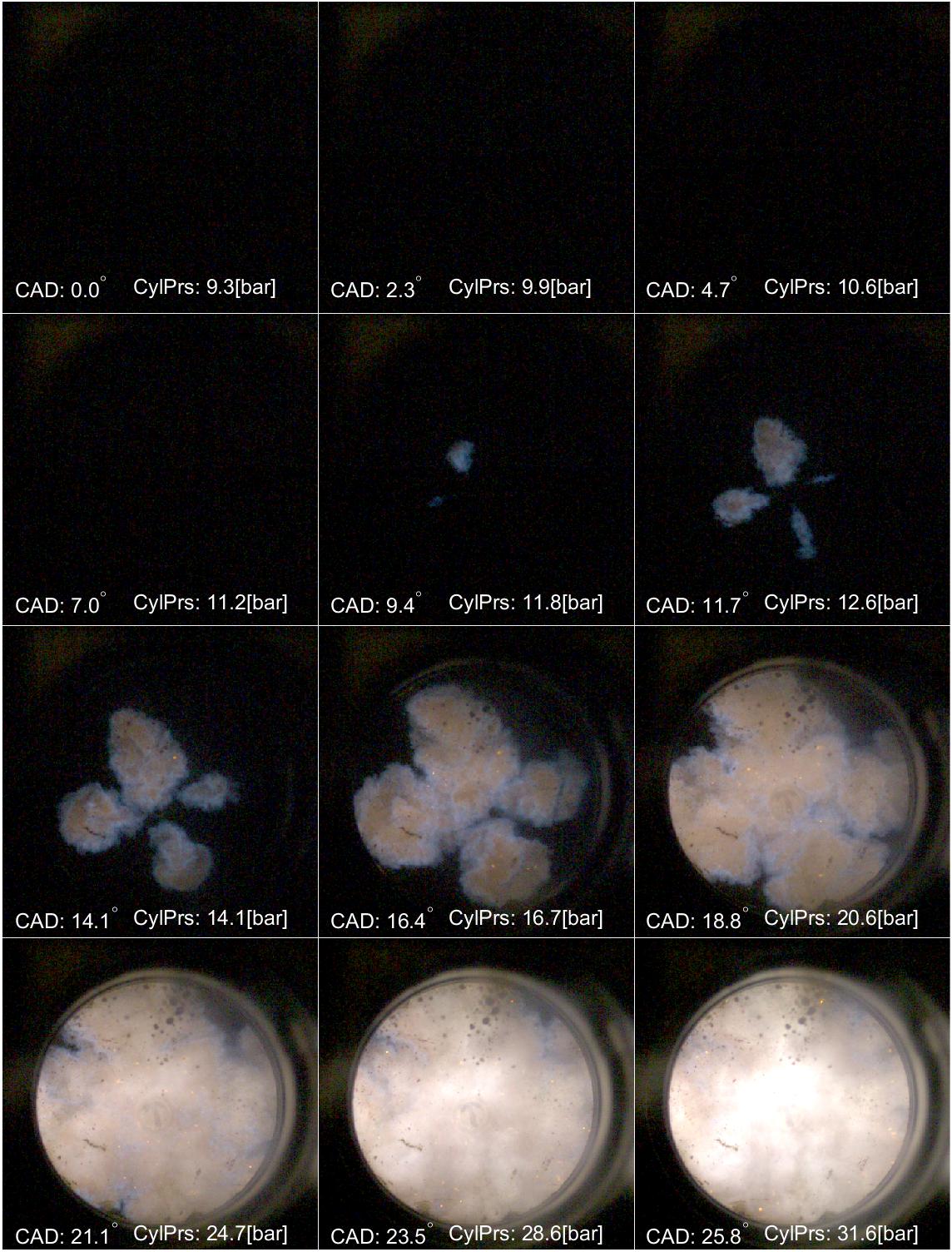
We currently use two single cylinder optical engines to investigate fundamental combustion phenomena in an applied setting. High speed imaging is acquired in-line with the cylinder (viewing the intake/exhaust valves) or from the side (viewing across the piston head). Imaging coupled with in-cylinder pressure measurements and exhaust gas analysis can provide a detailed picture of the combustion taking place.
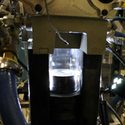
A 2.0 L single-cylinder, optically-accessible research engine. The engine cylinder head hardware is based on a modern 4-valve gasoline direct injection engine geometry. Axial and orthogonal optical access is available through piston window inserts and transparent cylinder liners. The aluminum cylinder head features a side-mounted fuel injector with dual overhead camshafts and 4 valves around a centrally mounted spark plug. The engine geometry uses a ø89.0 mm bore and 81.4 mm stroke, yielding 0.51 L displacement.
Recent publication:
M. Fatouraie, M. S. Wooldridge, S. T. Wooldridge. “In-cylinder Particulate Matter and Spray Imaging of Ethanol/Gasoline Blends in a Direct Injection Spark Ignition Engine,” SAE Int. J. Fuels Lubr. 6 (2013) 1-10.
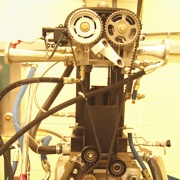
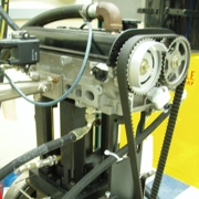
A base Ford Zetec-SE 1.25 L engine was modified to utilize one of the four cylinders. The aluminum cylinder head is equipped with fixed dual overhead cams with twin intake and exhaust valves. The engine bore of Ø71.9 mm, equipped with flat-top piston, with the stroke of 76.5 mm provided 0.31 L of displacement and a compression ratio of 10:1. The piston was modified to include a fused silica disc insert of Ø48.5 mm for optical access. The cylinder head is equipped with port fuel injection and a centrally mounted gasoline direct injection.
Recent publication:
M. Fatouraie, P. E. Keros, M. S. Wooldridge. “A Comparative Study of the Ignition and Combustion Properties of Ethanol-Indolene Blends During HCCI Operation of a Single Cylinder Engine,” SAE Technical Paper 2012-01-1124, (2012).
Diffusion Flame Burner
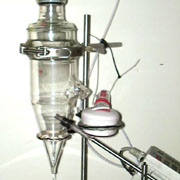

Our multi-element diffusion flame burner (a Hencken burner) provides a high temperature environment for gas phase combustion synthesis of nanostructured powders. Mixed phase precursors are provided using a bubbler system and a solid-phase particle feed system. Synthesized material properties (e.g. particle size, size distribution, morphology) are controlled by properties of the diffusion flame and the relative height of the collecting plate (i.e. residence time).
Recent publication:
S. D. Bakrania, M. S. Wooldridge. “The Effects of the Location of Au Additives on Combustion-Generated SnO2 Nanopowders for CO Gas Sensing,” Sensors 10 (2010) 7002-7017.
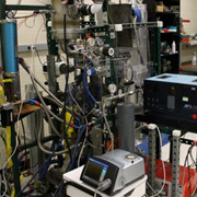
Constant Volume Combustion Chamber
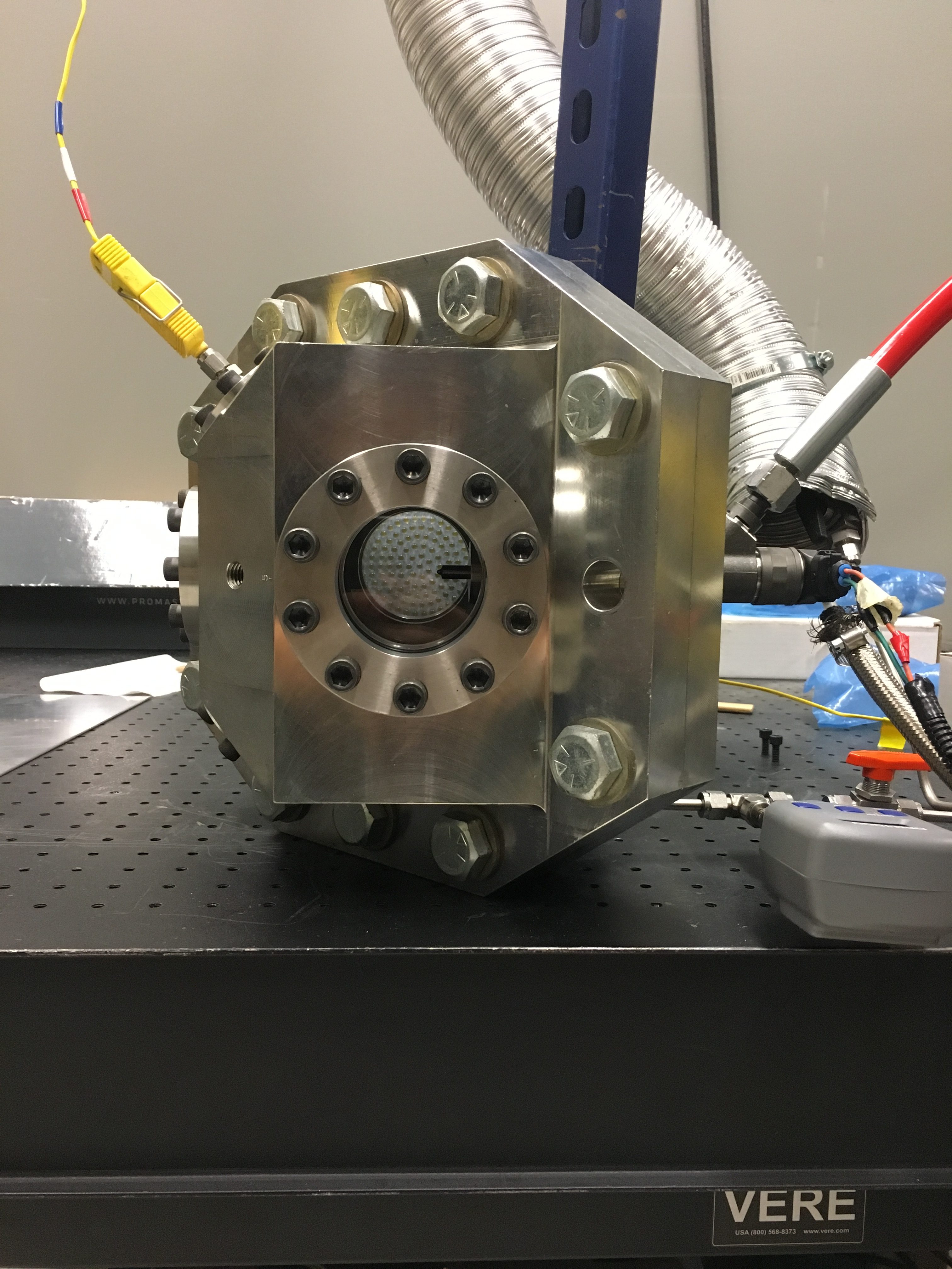
The constant volume combustion chamber (CVCC) has an internal spherical diameter of 12.4cm and is capable of pressures up to 100 bar with 3 optical access ports (2 perpendicular and 1 parallel) to image spray events. The chamber also has several other ports for instrumentation and measurement including a spark plug. Optical techniques employed with this system have been mie-scattering and backlit diffuse shadowgraph. The system is equipped with a diesel CP3 pump and has been tested with diesel fuel up to 2000 bar and with reference grade gasoline between 300-1600 bar.
Recent publication:
Medina, M., Fatouraie, M., and Wooldridge, M., “High-Speed Imaging Studies of Gasoline Fuel Sprays at Fuel Injection Pressures from 300 to 1500 bar,” SAE Technical Paper 2018-01-0294, 2018
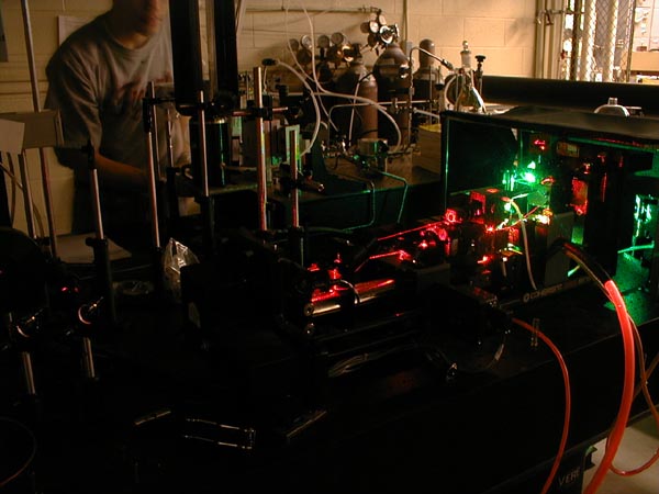
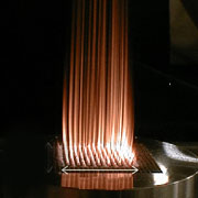
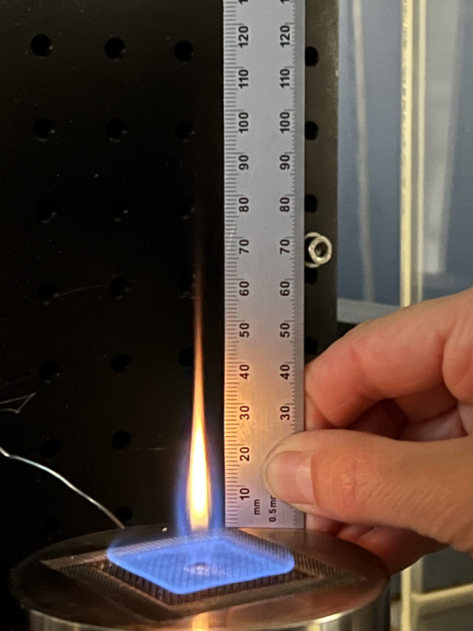
Stagnation Flow Reactor
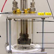
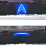
The stagnation flow reactor is used to isolate and study catalytic effects on combustion. Fuel oxidation, flame structure, and flammability limits are areas where catalyst/flame interactions play an important role in combustors. Different flame structures can be stabilized in our apparatus over a range of equivalence ratios and impinging velocities. Areas of interest that can be probed by the stagnation flow reactor include: novel catalyst materials for various applications such as lean NOx removal, renewable energy production via biomass reforming into ethanol, heterogeneous chemical mechanism development, and new combustion techniques such as low temperature combustion stabilized by a catalyst.
Recent publication:
J. T. Wiswall, M. S. Wooldridge, H. G. Im. “The Effects of Platinum on Propane/Air Stagnation Flow Flames,” Combustion Science and Technology 183 (2011) 540-553.